Much experimentation has been done in regard to determining what would
be suitable arrangements for Morse telegraph circuits that could be set
up and used during Civil War era re-enactments and similar activities.
There were several criteria that were deemed necessary to follow for
such circuits:
- The circuitry should be of a type that is as similar as possible to
what might have
been actually used in the mid 1860's, i.e. ground return, single wire.
- Instrument types should be similar in construction and coil
resistance value as those
actually used during the era, i.e. Morse relays, 150 ohm coil windings.
- Power sources should be electrically equivalent to that available in
the 1860's period, but safe, operationally practical, and dependable.
- Minimal hazards to people, property and animals, and minimal
environmental impact on the locations of the activity.
With these criteria in mind, experimentation was carried out by means of
actually constructing and testing a circuit to see how well it operated.
Ground return telegraph circuits using a single wire conductor insulated
from Earth, have some characteristics that are useful in this work. For a physically short
circuit, say less than a few miles, the resistance of the circuit is dominated by the path through the
earth. This may be partly due to imperfect ground connections, the rudimentary electrodes used for
grounding purposes. This situation can be used to advantage, especially for "shorter"
circuit lengths of a few hundred yards to a couple of miles or so.
For these high resistance circuits, we are forced into using low current
values. Because of this, we must also use high resistance (what are commonly called "main line")
telegraph instruments, wound with coil resistances of 120 to 150 ohms or so.
The reason for this is simply because we cannot safely force enough
current through such a high resistance circuit to operate low resistance (4 or 20 ohm etc.)
relays or sounders. It would take unsafe voltages to do so. The high resistance instruments
are designed to operate reliably on line currents of 50 milliamperes or so with limits
of roughly 30-60 Ma. These current values can be easily obtained in a grounded, single wire
circuit without the use of hazardous voltages at the power supply.
The experimentation that has been done was initially carried out with a
transformer-rectifier-filter power source connected to the commercial AC mains, and utilized an
auto-transformer (Variac) to allow adjustable power supply voltages. This was used to explore the
range of voltage which would be necessary to operate a grounded circuit of considerable length,
and with makeshift ground electrodes.
|
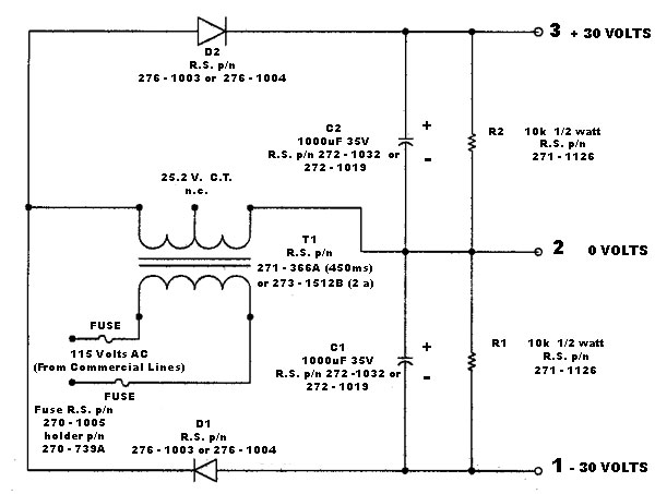
UNIVERSAL TELEGRAPH POWER SUPPLY |
 |
| Notes: |
- This power supply can be connected with terminal 1 to Earth, giving +30 volts at terminal 2, and +60 volts at terminal 3.
- Or, it can be connected with terminal 2 to Earth, giving -30 volts at terminal 1, and +30 volts at terminal 3.
- A third possible way it can be connected is to connect terminal 3 to Earth, then terminal 2 will be at -30 volts, and terminal 1 will be at -60 volts.
- The AC transformer winding should be equipped with an appropriate line cord and plug. Do NOT overfuse. The 1 amp fuses will carry the supply at full output.
- A 40 watt, 120 volt lamp, such as a tubular style, or appliance lamp, should be connected in series with all outputs of this supply except the earth-connected one. This lamp will provide isolation between multiple circuits "taking battery" from it as well as provide adequate short circuit protection in case the supply is inadvertently grounded or short circuited close in to the output. The filament will remain dark unless the current reaches approximately 90 mA, at which point it will begin to glow. A full short circuit will light the lamp to about half brilliance, and limit the current to about 150 mA.
|
A test circuit was constructed using a large spool of insulated, 22 ga.
tinned copper hookup wire, three 150 ohm Morse relays, telegraph keys, and ground electrode
consisting of a short iron rod pushed a couple of feet down into damp moist earth. The large spool of
wire procured for the experiment was 3300 feet of four conductors, splices being made at the
ends of the spool so as to form one single conductor 13,200 feet in length, which is approximately
2 1/2 miles. the conductors were connected in series in such a fashion as to eliminate inductive
effects by cancellation. That is, the current transits the spool of wire four times, twice in each
direction, thus effectively cancelling any inductive effects that may be due to the wire being all wound on a
large spool. I did not have enough room available to string it all out in one length.
The experimentation began by connecting this spool of wire in series
with two 150 ohm Morse relays, a 120 volt 40 watt incandescent lamp, and the Variac adjustable power
supply. Earth at the power supply end was "Power Neutral". The "far" end of the spool of wire was
connected to a third 150 ohm relay, and then to a two foot 3/8 inch diameter (rusty) steel rod,
pounded down into the soft ground at the rear property fence, fifty yards or so out in the back of the
house. The end result was a Morse circuit with two instruments and "Battery" at one end, ground and a
third instrument at the "far" end 2 1/2 miles distant circuit-wise. The 120 Volt 40 Watt light bulb was
included as a protection device, to prevent damage in case the circuit was inadvertently grounded too
close to the supply end. The filament remains dark in such a lamp until the current approaches about 90 Ma,
and its series resistance with a dark filament is negligible in the circuit. It was and is good
practice to include such a lamp in ANY rectifier/filter type power source used for telegraph work.
The circuit would not operate at all until the voltage was increased to
about 40 volts, as measured with a switchboard voltmeter (11,200 ohms meter resistance).
At this point, the the circuit closed weakly with about 20 Ma flowing.
The instruments could be adjusted to work with this, but were near the
extreme end of their range. Once adjusted however, the circuit was entirely workable in all respects.
The voltage was raised until the circuit current was 55 Ma. This
resulted when the voltage reached approximately 60 volts. This is an adequate, but "non-hazardous" value
of DC voltage, and the rest of the experiments were carried out with this as a limit for
terminal voltage supply. Higher voltages up to about 130 volts were tried, but this only resulted in higher
current in the circuit, and extra series resistance needed to be added to keep the current near the 50 Ma
desired value. More than 60 volts therefore, was unnecessary. The 40 to 60 volt open circuit
battery voltage was more than adequate to properly operate the circuit with three or four 150 ohm instruments cut in.
The circuit length was varied by changing how much of the wire on the
spool was included in the circuit. It was found that the circuit current only varied a few (less
than 5) Ma. when 1/4, then 1/2, then the ENTIRE spool of wire, all 2 1/2 miles of it, was cut out.
From this, it was indicated that the resistance in the circuit contributed by the ground path was dominant.
For all practical purposes, in this particular situation, the LENGTH of the wire conductor in the
circuit was immaterial. This means that with this circuit, it would be possible to work from a
few yards to over 2 miles without doing anything to the voltage or current at the supply.
This is an ideal setup for a re-enactment activity, as it would make
establishing and rearranging circuits to various "offices" fairly simple. The circuits could all
"take battery" at one central point, and all that would be necessary at the distant end would be a simple
ground connection of some kind. Shortening or lengthening of lines could be easily done by simply
relocating the end of the circuit and its ground connection. Additional offices could be "cut
in" at any intermediate point along any line without disturbing the circuit values to any appreciable degree.
A different power supply was devised, that has fixed output voltages,
and can be connected in a variety of ways to supply "Telegraph Battery" for this kind of
circuit. This power supply uses readily available parts from Radio Shack , and is
designed so that it can be plugged into a GFI AC outlet and be safely used for grounded telegraph circuits.
The supply may be connected with Earth and provide both positive and
negative 30 volts, or can be connected to provide either positive 60 volts or negative 60
volts with respect to Earth. 120 Volt , 40 watt lamps should always be connected in series with the
power supply outputs and the telegraph circuit for safety reasons already noted.
Ground connections were also experimented with. The simple driven rod
proved adequate in moist earth. A rifle bayonet would also work as well. A chunk of wire
screen was attached to a wire and tossed into a large mud puddle nearby. This also allowed
full line current to pass.Other things tried were a keyhole saw blade shoved into the earth. a
steel fence post. etc. All seemed to work effectively.
Other "grounds" that can be considered would be railroad rails, well
casings, large metal building frames, driven pipes or rods, buried plates or metal cans, or
coils of bare wire, etc. The simplest, and perhaps the most overlooked possibility, is a river,
creek, pond, or other body of water. A few yards of bare wire, or a wire attached to a large
chunk of metal screen can or bucket, sunk in such a body of water will provide a nearly
perfect ground, and be extremely environmentally friendly. No trace of its use remains when it is removed and hauled away.
The end result of the experiments show that it is possible to erect
simple telegraph wires in the traditional fashion, and operate them at almost any distance apt
to be encountered in a typical re-enactment activity, with simple power sources of fairly
low, non-hazardous voltages. The line wires of course must be insulated as perfectly as
possible from Earth, but it has been shown that the circuit length is mostly immaterial even
with smaller size wire as long as the battery voltage is sufficient. Since but a single
wire is required between "stations" or "offices", the circuitry is simple and straightforward.
Instruments can be the more common high resistance "mainline" types that most people have in
their collections. Ground connections can be rudimentary and easy to establish. "Battery"
can be supplied at one end or both ends of the circuit, as circumstances dictate.
The one other aspect that needs to be addressed is lightning protection.
Any time a wire is strung for any length out of doors, it becomes a prime target for
lightning strikes. Any such telegraph wire should be, at MINIMUM, provided with simple, air-gap
arrestors, such as those provided on peg-strap switchboards, or simple cut-outs with air
gap protectors., and a ground electrode at each station or office. The air gap type is
adequate in most cases, although NOTHING will protect against a direct strike.
In any event, make sure ALL instruments are DISCONNECTED entirely from
the circuit during any nearby electrical storm with visible lightning, and stay away from
working on poles, lances or other outside parts of the line during such storms. For safety's sake,
ground the wires at all stations until the storm has passed on.
Ed Trump, Fairbanks, Alaska ~ April 1998.
Note... Author is not responsible for any injury or damage to people,
property or animals due to use or misuse of any of the information presented herein.